 |
1樓
巨大八爪鱼
2017-1-16 14:07

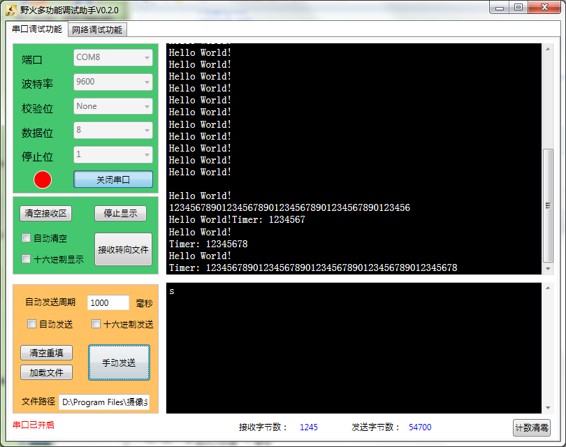
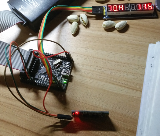
【程序运行效果】
 |
 |
2樓
巨大八爪鱼
2017-1-16 14:08

【程序】
#include <stm32f10x.h>
inline uint32_t _BV(uint8_t n)
{
return (1 << n);
}
// 数码管扫描类
class Scanner
{
private:
static const uint8_t table[]; // 数码管字形表
void input(uint8_t data); // 74HC595串行输入
void output(void); // 74HC595并行输出
public:
Scanner(void); // 初始化GPIO口
void delay(void);
void display(uint16_t num, uint8_t start = 0, uint8_t len = 3, bool dot = false); // 动态扫描数码管, 显示len位数字num, 个位位于start处的数码管
void displayAt(uint8_t pos, uint8_t num, bool dot = false, bool delay = true); // 在指定数码管上显示指定数字
};
const uint8_t Scanner::table[] = {0xc0, 0xf9, 0xa4, 0xb0, 0x99, 0x92, 0x82, 0xf8, 0x80, 0x90};
Scanner::Scanner(void)
{
RCC->APB2ENR |= RCC_APB2ENR_IOPBEN;
GPIOB->CRL = 0x30000000; // PB7~9设为输出
GPIOB->CRH = 0x00000033;
}
void Scanner::delay(void)
{
uint16_t i;
for (i = 0; i < 20000; i++);
}
void Scanner::input(uint8_t data)
{
uint8_t i;
for (i = 0; i < 8; i++)
{
GPIOB->BRR = GPIO_BRR_BR9; // SCLK=>PB9
if (data & 0x80)
GPIOB->BSRR = GPIO_BSRR_BS7; // DIO=>PB7
else
GPIOB->BRR = GPIO_BRR_BR7;
data <<= 1;
GPIOB->BSRR = GPIO_BSRR_BS9;
}
}
void Scanner::output(void)
{
GPIOB->BRR = GPIO_BRR_BR8; // RCLK=>PB8
GPIOB->BSRR = GPIO_BSRR_BS8;
}
void Scanner::display(uint16_t num, uint8_t start, uint8_t len, bool dot)
{
// 扫描方向是从右到左
uint8_t i;
for (i = 0; i < len; i++)
{
displayAt(start + i, num % 10, dot && i == 0);
num /= 10;
}
}
void Scanner::displayAt(uint8_t pos, uint8_t num, bool dot, bool delay)
{
if (dot)
input(table[num] & 0x7f);
else
input(table[num]);
input(_BV(pos));
output();
if (delay)
this->delay();
}
// 串口通信类
class CommPort : public Scanner
{
private:
uint8_t num;
uint8_t seconds;
public:
CommPort(void);
void run(void);
void sendString(const char *s); // 串口发送字符串
void setNum(uint8_t num);
void timeUp(void);
};
CommPort::CommPort(void) : num(0), seconds(0)
{
RCC->APB2ENR |= RCC_APB2ENR_IOPAEN | RCC_APB2ENR_USART1EN;
GPIOA->CRH = 0x000008b0; // PA9(TX)设为复用50MHz推挽输出, PA10(RX)设为输入
GPIOA->BSRR = GPIO_BSRR_BS10; // PA10带上拉输入
// 波特率9600=72MHz/16x, x=468.75
// 468=0x1d4, 0.75=12/16, 12=0xc
USART1->BRR = 0x1d4c;
USART1->CR1 |= USART_CR1_UE | USART_CR1_RE | USART_CR1_TE | USART_CR1_RXNEIE; // 打开串口, 允许发送和接收, 开接收中断
NVIC->ISER[USART1_IRQn / 32] |= _BV(USART1_IRQn % 32);
// 配置定时器
RCC->APB2ENR |= RCC_APB2ENR_TIM1EN;
TIM1->ARR = 9999;
TIM1->PSC = 7199;
TIM1->DIER |= TIM_DIER_UIE;
NVIC->ISER[TIM1_UP_IRQn / 32] |= _BV(TIM1_UP_IRQn % 32); // 开定时器溢出中断
TIM1->CR1 |= TIM_CR1_URS;
TIM1->EGR |= TIM_EGR_UG;
TIM1->CR1 &= ~TIM_CR1_URS;
TIM1->CR1 |= TIM_CR1_CEN;
}
void CommPort::run(void)
{
sendString("\nHello World!\nTimer: ");
while (1)
{
display(num);
display(seconds, 6, 2, true); // 秒数(两位)
displayAt(5, TIM1->CNT % 10000 / 1000); // 毫秒数
}
}
void CommPort::sendString(const char *s)
{
while (*s)
{
while ((USART1->SR & USART_SR_TC) == 0);
USART1->DR = *s++;
}
}
void CommPort::setNum(uint8_t num)
{
this->num = num;
}
void CommPort::timeUp(void)
{
seconds++;
if (seconds >= 100)
seconds = 0;
USART1->DR = '0' + seconds % 10;
}
CommPort *pCp; // 供中断函数用的指针
int main(void)
{
CommPort cp; // 两个类的构造函数都要执行
pCp = &cp;
cp.run();
return 0;
}
// 注意在C++程序中中断函数要加前缀
extern "C" void TIM1_UP_IRQHandler(void)
{
// 定时器溢出中断
TIM1->SR &= ~TIM_SR_UIF;
pCp->timeUp();
}
extern "C" void USART1_IRQHandler(void)
{
// 串口接收中断
if (USART1->SR & USART_SR_RXNE)
pCp->setNum(USART1->DR);
}
|
 |
3樓
巨大八爪鱼
2017-1-16 14:14

本人在测试此程序时,为了方便起见,PA9,PA10上是接的蓝牙串口模块。
 |
 |
4樓
巨大八爪鱼
2017-1-16 14:24

不过呢,51单片机没法用C++编写程序。因为编译的时候Keil uVision5直接就失去了响应:  |
